With the bluesmirf project complete I want to say that I am very impressed with "Making Things Talk" by Tom Igoe. The book is excellent! I did have problems with the bluesmirf from sparkfun because they put out a revised unit with a different (looks like a better one, but I can't compare) bluetooth module on it. The command set is different from what is in "Making Things Talk", but once I realized that the module was different I was able to get going again with the datasheets on the sparkfun bluesmirf product page. This was no fault of the book and from the viewpoint of a normal bluesmirf user no big deal, they would just the datasheet. I have seen other examples of computer hardware where the model number is the same but the hardware under the cover is much different. As a general rule looking at the datasheet helps big time. Once I got over being intimidated by them they were a big help, I don't necessarily read the whole thing either, they work as a quick reference too.
I wanted to test the waters before I committed to putting out the money on the hardware for the projects. This stuff is really new to me and the book is exactly what I had been looking for. There are many projects on the internet but I have never seen a group like in this book that are so useful and cover so much.
I can't wait to see Tom's next book if he decides to do one!
Saturday, December 29, 2007
Monday, December 24, 2007
Difficult Problems Sometimes Have Simple Causes!
Or the other way around. Had to figure out quite a bit but now it looked like it was clear sailing. All I needed to do to finish with the bluetooth was have it work with the Monski Pong. Well for some reason it did not work. When I ran it the Processing program locked things up and the window for playing Pong locks up and stays blank. This is the same program I ran that worked through the USB cable to the Arduino. After this I could not communicate with BlueSMiRF through hyperterminal until I turned the BlueSMiRF off and on.
I went through variations of this numerous times. The Arduino Alpha 010 utility also would not view serial data in the serial monitor throught the bluetooth. This is likely unrelated to the Monsky Pong not working though it was not clear earlier. I also tried to upload the Arduino program though the bluetooth COM but it didn't work either. I imagine it should be possible.
I even had to unplug and plug in again the usb bluetooth dongle one time. This is after restarting the system and turning off and on the BlueSMiRF several times without the problem clearing up. I realized that during the restart system cycle the usb ports still get power. This happened only once and I was trying all kinds of crazy things and don't remember what I did that particular time. The error on the pc was that it would not connect and gave the error message "There was a security error. You may need to redo pairing." or some close phrasing.
I was using the correct COM port, the same ones I have been using all along in hyperterminal.
At times like this I find it helpful to go back to a state where things were working and go over everything in order of what seems most likely to be at fault. If anything I was sure the hardware was not broken, and only cutting out because I ran the processing program. I finally went over the serial commands in the processing program and found that I had somehow deleted or not put in the baud statement in:
myPort = new Serial(this, Serial.list()[1], 9600);
For lack of 9600 I spent a couple hours going over everything!
It works now. Though I am not quite sure that this is what really fixed things.
A couple of observations. The Monski Pong takes longer to open the play window when using the bluetooth vs. the usb cable to the arduino. I think it must be the time to establish the serial connection through bluetooth. Another thing is that the analog input from the pots and flex sensor is "jittery" the values oscillate and it makes the paddles in monski pong jitter up and down.
On to the next project!
Arduino Over Bluetooth!
The Arduino is transmitting over bluetooth. Not as easy to do it the first time but now that it is working and I have learned the way of it, it is really easy. I had to learn more than I thought I would but that isn't a bad thing. And now that I know how to get it running and that it does actually work, I can start thinking about doing something useful and fun with it. The next step will be to go back and have it work with the Monski Pong Program.
The first major step was learning to connect the blueSMiRF through the FT232R USB to Serial converter and talking to it using Hyperterminal. Real important was that when communicating with the BlueSMiRF the baud has to be 115200, otherwise it does nothing. I could not do without the Command Set Datasheet for this. It is a must have! The one problem I had I mention in the last post, when setting the Flow Control setting in Hyperterminal I had to set it to None, where the Datasheet specifies Hardware. Another thing is that when in CMD mode some of the commands work in lower and upper case and some don't. Just something to keep in mind.
Next was to enter command mode on the BlueSMiRF over Bluetooth. There is a clock allows this for 60 seconds after the BlueSMiRF starts up.
After that was communicating between Hyperterminal windows using the bluetooth as a serial port connection. It worked very well, but had a few hiccups. When communicating between the laptop and desktop if the laptop went to sleep I had to reboot the laptop to re-establish communication. If I was in CMD mode on the blueSMiRF throught the FT232R and tried to connect through a Hyperterminal window by bluetooth it would crash the Hyperterminal. There were a couple times where I did something that cause the communication to stop but could restart by powering off and on the BlueSMiRF. I spent alot of time playing around with different settings and running the the BlueSMiRF on the arduino, the FT232R, on 1 computer and on 2 (BlueSMiRF on laptop and bluetooth dongle on Desktop)
The final thing was to run BlueSMiRF on the Arduino. The wiring is very simple to hookup the BlueSMiRF, connect power to the +5v or 3.3v , gnd to ground, and TX to the RX and RX to the TX on the Arduino. This is where I had Hyperterminal windows open to the Arduino through USB, the BlueSMiRF over Bluetooth. First time it should have been working as a serial port connection but it wasn't, this is where I think I had trouble at the very start. What I learned was that the BlueSMiRF wants to go at 115200 baud, the Arduino at 9600. Once I set the BlueSMiRF at 9600 baud it started transmitting the serial data from the arduino to the hyperterminal window on my desktop.
(I used the roving networks command for temporarily changing the baud. U,9600,N and CR. Type su, to set it so it is in the memory and it will stay after power down.
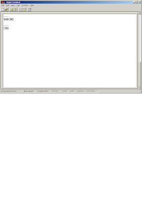
For my own future reference, the settings can be gotten from the BlueSMiRF by getting into Command Mode by typing $$$ in the terminal window.
Then type D for settings and E for advanced settings. I changed the baud by typing su, 96 The baud is set to 9600 (only the first 2 digits are needed)
Settings
d
***Settings***
BTA=00066600666F
BTName=FireFly-666F
Baudrt(SW4)=115K
Parity=None
Mode =Slav
Authen=0
Encryp=0
PinCod=1234
Bonded=0
Rem=000272CC10D6
e
***ADVANCED Settings***
SrvName= SPP
SrvClass=0000
DevClass=1F00
InqWindw=0200
PagWindw=0200
CfgTimer=60
StatuStr=NULL
su,96
AOK
d
***Settings***
BTA=00066600666F
BTName=FireFly-666F
Baudrt=9600
Parity=None
Mode =Slav
Authen=0
Encryp=0
PinCod=1234
Bonded=0
Rem=000272CC10D6
The first major step was learning to connect the blueSMiRF through the FT232R USB to Serial converter and talking to it using Hyperterminal. Real important was that when communicating with the BlueSMiRF the baud has to be 115200, otherwise it does nothing. I could not do without the Command Set Datasheet for this. It is a must have! The one problem I had I mention in the last post, when setting the Flow Control setting in Hyperterminal I had to set it to None, where the Datasheet specifies Hardware. Another thing is that when in CMD mode some of the commands work in lower and upper case and some don't. Just something to keep in mind.
Next was to enter command mode on the BlueSMiRF over Bluetooth. There is a clock allows this for 60 seconds after the BlueSMiRF starts up.
After that was communicating between Hyperterminal windows using the bluetooth as a serial port connection. It worked very well, but had a few hiccups. When communicating between the laptop and desktop if the laptop went to sleep I had to reboot the laptop to re-establish communication. If I was in CMD mode on the blueSMiRF throught the FT232R and tried to connect through a Hyperterminal window by bluetooth it would crash the Hyperterminal. There were a couple times where I did something that cause the communication to stop but could restart by powering off and on the BlueSMiRF. I spent alot of time playing around with different settings and running the the BlueSMiRF on the arduino, the FT232R, on 1 computer and on 2 (BlueSMiRF on laptop and bluetooth dongle on Desktop)
The final thing was to run BlueSMiRF on the Arduino. The wiring is very simple to hookup the BlueSMiRF, connect power to the +5v or 3.3v , gnd to ground, and TX to the RX and RX to the TX on the Arduino. This is where I had Hyperterminal windows open to the Arduino through USB, the BlueSMiRF over Bluetooth. First time it should have been working as a serial port connection but it wasn't, this is where I think I had trouble at the very start. What I learned was that the BlueSMiRF wants to go at 115200 baud, the Arduino at 9600. Once I set the BlueSMiRF at 9600 baud it started transmitting the serial data from the arduino to the hyperterminal window on my desktop.
(I used the roving networks command for temporarily changing the baud. U,9600,N and CR. Type su,
For my own future reference, the settings can be gotten from the BlueSMiRF by getting into Command Mode by typing $$$ in the terminal window.
Then type D for settings and E for advanced settings. I changed the baud by typing su, 96 The baud is set to 9600 (only the first 2 digits are needed)
Settings
d
***Settings***
BTA=00066600666F
BTName=FireFly-666F
Baudrt(SW4)=115K
Parity=None
Mode =Slav
Authen=0
Encryp=0
PinCod=1234
Bonded=0
Rem=000272CC10D6
e
***ADVANCED Settings***
SrvName= SPP
SrvClass=0000
DevClass=1F00
InqWindw=0200
PagWindw=0200
CfgTimer=60
StatuStr=NULL
su,96
AOK
d
***Settings***
BTA=00066600666F
BTName=FireFly-666F
Baudrt=9600
Parity=None
Mode =Slav
Authen=0
Encryp=0
PinCod=1234
Bonded=0
Rem=000272CC10D6
Sunday, December 23, 2007
Bluetooth Communication Established!

Had some time today to try some things out with the BlueSMiRF.
I was able to communicate between two computers (and 2 windows of hyperterminal), one using the bluetooth USB adapter, and the other using the FT232R USB to Serial Converter connected to the sparkfun bluetooth modem through the TX and RX connections. It was using real "honest to goodness" radio waves! Wireless! Real text! After having it not work, it really did seem miraculous when it did!
I had some peculiar things happen that will probably be explained when I go over the Roving Networks User Guide again. I had the bluetooth blueSMiRF modem hooked up to my laptop (through the FT232R) and had it communicating with my desktop PC (USB bluetooth)
To connect to the BlueSMiRF, I had to set the baud to 115200. This is stated in the user guide. If I played around with the baud settings in the 2 windows of hyperterminal sometimes it would be fine, and other times not.
Also my laptop went to sleep and upon waking it would not talk with the blueSMiRF. Everything seemed fine except it would not go into Command mode or communicate. I had to reboot the laptop.
After that it would talk with the laptop in Command mode and (out of Command mode) talk with the Desktop.
It would be inconvienient if the bluetooth stopped working when the laptop went to sleep and requrired a reboot work again. If this is "just how it is" at least I would know and deal somehow. I suspect there is a reason and way to have it not do that.
Don't know for sure yet.
Also the setting in Hyperterminal I used on the laptop for "Local Configuration" as it is called in the Roving Networks User Guide (Roving Networks Bluetooth Serial Module Command Set Version 4.26) (Page 6) is the exact opposite of what is suggested. Under the Flow Control setting I used None, where in the manual it says use Hardware.
If I use Hardware Flow Control, it doesn't work. I don't know why this is (yet) but it was important to me for obvious reasons.
I can connect in Command Mode from the bluetooth connection, keep in mind that there is timer and the the default is 60 seconds from startup. I can connect with Flow Control set to None or Hardware. In the manual it suggests Hardware for this also.
I am just mentioning this because sometimes things wont work as instructed, very important things. Maybe I did something somewhere else incorrect to cause this, maybe not. In this case experimenting doesn't hurt.
Next step is to get the Arduino to transmit over the BlueSMiRF. I will save that for tomorrow.
Tuesday, December 18, 2007
Back to Bluetooth
I spent a couple days trying to get the BlueSmiRF to work. Two very frustrating days.
First it didn't work with the Monski Pong. It did connect with the bluetooth on my PC but it would drop the connection and was generally not working at all as a serial port. I then went into troubleshoot mode and the first suspect was the bluesmirf module itself. I had the sparkfun.com Bluetooth Modem - BlueSMiRF (SKU#: WRL-00582) that "Making Things Talk" specified, that should be good. (not so, but it should work out anyway)
Next, I setup the FT232R USB to RS232 converter with the bluetooth to see if I could get some assurance that the bluesmirf was working by going through the AT commands from a terminal program. That wasn't working either for the reasons I'll get into shortly.
As it turned out the AT commands that "Making Things Talk" has in their walk through of the bluesmirf did not work! After trying it various ways, many various ways I decided to go back to the beginning. I started looking over the spec sheet on the sparkfun site and realized that the part about "new Roving Networks bluetooth module. The command set is not compatible with the previous Mitsumi module" was perhaps important! Shame on me for not reading the details.
I still have not tried the bluetooth serial port but have just now been able to communicate with the bluetooth via the FT232R! Basically from reading the Roving Networks documents on the bluesmirf. In hindsight I should have done it at the beginning, but the book walk throughs were going so well! Once you have it working it is quite talkative!
Next step is to go back and get it to work with the monski pong program and finish of the setup from the terminal.
So be warned, if you are using the bluesmirf the new command set is different.
This is what worked for me to communicate with the bluesmirf through the FT232R USB to R232 converter. (sparkfun Breakout Board for FT232RL USB to Serial (SKU#: BOB-00718)
Step 1: Hook up the bluesmirf and FT232R board as shown on pg 76, Fig 2-9. (exception I attached the 3.3v power to the bluesmirf.)
Step 2:
1. Open HyperTerminal.
The "Connection Description" Window will appear.
2. In the Name box, I typed j, you can type whatever you want, mostly.
3. Click OK.
The "Connect to" window will appear.
4. In the Connect to window, pick the com port for the FT232R.
The "COM Properties" window will appear.

5. In the Bits per second dropdown, select 115200. The 9600 baud selection didn't work for me and the Roving Networks docs mention 115200 as the desired baud.
6. In the Data bits entry, select 8.
7. In the Parity entry, select None.
8. In the Stop bits entry, select 1.
9. In the Flow control entry, select None.
10. Click OK.

This will connect to the COM port, but you must not have any other application using that COM port. Only one application can use a COM port at at time.
12. On the main hyperterminal window click on disconnect so you can change the settings.
13. go to File, Properties.
This will show the "Properties" window.
14. Select "Settings" tab, click the "ASCII setup" button.
This will show the ASCII window and options.
15. Check the Send line ends with line feeds.
16. Check the Echo typed characters locally.
17. Check the Append line feeds to incoming line ends.
18. Check the Wrap lines that exceed terminal width.
19. Select OK.
You will be back on the Properties window.
20. Select OK.
You will be back on the main hyperterminal window.
21. Click Call (the phone), (you should be on the main hypertermial window.
This should connect you to the port, look at lower lefthand corner for "connected".
22. Type --- then carriage return and first time it does nothing, or replies END.
23 Type $$$ then carriage return and it should reply CMD.
24 Type --- then carriage return and it should reply END.
Try the other commands you need according the the Roving Networks documentation (assuming you have the bluesmirf with the Roving Networks bluetooth)
H puts a lot of stuff up, it stands for Help.

Monday, December 17, 2007
Thermocouple continued
Didn't do much today, had other things to do.
Did find out that int(variable) will convert a float variable to int. That is change 58.93929399234 to 58. So simple.
I had thought about a decoupling capacitor to fix my fluctuating readings problem. Didn't do anything until Pete mentioned I should try it. Found a couple links. One is about decoupling capacitors in general and sounds pretty reasonable. And another that shows one in schematic with a AD595 in use. It is a page on using the AD595 thermocouple IC with a Basic Stamp.
I tried values from .01uF to 1uf between the +5V input and ground, and as far as I can tell it doesn't make any difference. I tried smoothing the output by putting a .04uF capacitor there and that cut the fluctuation down by half. At this point I don't think I am going to do anything until I can find something that really works, and I know why. It works well enough and for what I need it for a plus/minus a degree is not important. Maybee it is normal. I don't think so though.
I went back to take another look at the k type thermocouple. It reads 0 volts, not too good. I tried the other K type I have and though it does read, the serial output reads very erratic. The data from the serial monitor looks like this:
61
0
0
0
0
61
0
0
0
0
63
0
0
0
0
Etc.
This does not make me happy!
The emesys.com site has a lot of Basic Stamp application stuff.
I might try the max digital thermocouple ic.
I am going to think about this one a bit and do some more research.
Sunday, December 16, 2007
Temperature Measurements Simple But Hard


I decided to test my new "understand" by trying a "simple" project which would use what I learned of serial communication and Arduino and Processing programming.
Perseverance got me through. I did learn quite a bit and in the end it was rather simple, just about as simple as I imagined it to be, except for all the learning I had to go through.
All I wanted to do was wire up a AD595 "Monolithic Thermocouple Amplifiers with Cold Junction Compensation" (click this to checkout the datasheet, it is what I used to wire up the AD595)to take the 10mV/Deg Celsius output and read it with the Arduino analog input and send it to the PC over the USB serial connection. Then using Processing to convert that data into a real Celsius and Fahrenheit temperature output.
I had several problems, first the K type thermocouple was not working correctly, I substituted it with a second that did work and reassured me that the IC was working correctly. I finally decided to use the internal ability of the AD595 to measure temperatures, they call it a "Stand-Alone Celsius Thermometer" if you are looking for it on the datasheet.
I decided that using the "stand-alone" feature would ease my troubleshooting. I also hooked up my voltmeter to measure the output mV reading of the AD595 to make sure it really was doing what it was supposed to. I recommend this step since I did have a K-type thermocouple that was not reading at all. It helps to know that the individual subsections are working.
I tried to do the programming of the Arduino with as little help from existing code as possible, also I decided I would also only set up the AD595 from the data sheet only also. More or less worked and I spent a lot of time reading the data sheet and reading the Help, Reference section of the Arduino page and Processing page, which were thankfully actually helpful! I did fall back on the code from Making Things Talk for troubleshooting the serial connection, and without that I think I would have had a much harder time. Having something that works to compare against really makes a big difference.
Next I set up the Arduino to take the mV reading from the AD595 through one of the analog inputs. This went fairly well and I could view the serial input through the serial monitor quite well. One thing I did notice and have not yet done anything with is that the values will fluctuate on the analog input. I don't know why but I found it annoying. I don't know if it is picking up some stray AC signal but I just don't like it!
I setup the Processing program to read the serial input which was just the analog input value, had to convert to mV, (mostly to troubleshoot) then convert to Celsius by a somewhat inaccurate conversion method of dividing the mV reading by 10. It is close but if you look at the data sheet there is some divergence from this in their tablulation of mV vs. temperature.
I hope to get into refining the Processing program but for now I am happy that it worked. Probably the first thing is to setup the "handshake" serial transfer method that ends up project 1 in Making Things Talk.
Processing Program to read the serial input and do conversions to show the temperature in Farenheit, Very rough, just got it working rough. Some of it may not make sense and be wrong! I was just happy that I finally got the temperature to read correct within a few degrees of my RadioShack digital thermometer!
/*
Temperature reader
Program Language: Processing 0133 Beta
Author: Lee Cavanagh
Revision:.1
Date: 12/15/07
Program reads serial data sent from an Arduino reading output from
a AD595AQ "Monolithic Thermocouple Amplifier
with Cold Junction Compensation"
Data is read through a analog input that coverts the 10mV/Deg C AD595 output
to a value within the range of 0-1023.
*/
import processing.serial.*; //Import the processing serial library
int linefeed = 10; //Linefeed in Ascii
Serial myPort; //The serial Port
PFont myFont; //Adds Font for displaying Temperature
int fontSize = 32; //sets the size of the Text
float rawTempData = 0.0; //the raw input of the temperature data
float tCelsius = 0.0; //temperature converted to Celsius
float tFarenheit = 0.0; //terperature converted to Farenheit
String myString = "0"; //input string from serial port
float miliVTemp = 500.0;
void setup() {
size (640,480); //sets the size of the display window
//uses font from system
PFont myFont = createFont(PFont.list()[2], fontSize);
textFont(myFont);
// list the available serial ports
//println(Serial.list());
//sets serial port
myPort = new Serial(this, Serial.list()[1], 9600);
//Read from buffer until it hits a linefeed.
//The linefeed tells it that it is at the group or piece of data I want
myPort.bufferUntil(linefeed);
}
void draw() {
background(100,204,0);
//Print the temperature:
text("TEMP: " + tFarenheit + " ºF" , 10, 50); //should print the temp in the middle of the screen
//println("Temperature : " + tFarenheit + " ºF");
}
void serialEvent(Serial myPort) {
//read serial buffer
String myString = myPort.readStringUntil(linefeed);
//if you got any bytes other than the linefeed it trims:
if (myString != null) {
myString = trim(myString);
//split the string at the commas
//and convert the sections into integers:
int sensors[] = int(split(myString, ','));
//pritn out the values you got:
for (int sensorNum =0; sensorNum < sensors.length; sensorNum++) {
print("Sensor " + sensorNum + ": " + sensors[sensorNum] + "\t");
//sets rawTempData equal to sensor[0]
rawTempData = sensors[0];
miliVTemp = rawTempData/1024*5.0*1000; //converts input to mV
println("miliVTemp=" + miliVTemp);
}
//add a linefeed after all the sensor values are printed:
println();
}
// text(myString, 10, 200);
//rawTempData = int(myString); //Puts the value into rawTempData
//convert to Celsius:
//Divide output of AD594 and you get the approx Celsius Temp
//There is some error as compared to the Manufacturer Datasheet
tCelsius = miliVTemp / 10.0 ;
//Convert C reading to Farenheit
tFarenheit = ((tCelsius * (1.8)) + 32);
println("Temperature : " + tCelsius + " ºC");
}
Arduino program to read the AD595 Thermocouple IC
/*
Program Language: Arduino
Author: Lee Cavanagh
Revision:.1
Date: 12/15/07
Program reads a AD595AQ Monolithic Thermocouple Amplifiers
with Cold Junction Compensation through a analog input and covert the 10mV/Deg C
to a analog input within the range of 0-1023.
That value will be sent through the serial USB by the Arduino to be read by the PC
*/
int temperature = 0; //value for the temperature voltage from the AD595
//converted to analog input value, will have to convert it at the PC to a real value
int tempSensor = 2; //analog input pin for temperature voltage input
void setup() {
//opens serial port to pc, rate to 9600
Serial.begin(9600);
}
void loop() {
//reads the analog sensor
temperature = analogRead(tempSensor);
//Prints the results from the analogRead
Serial.println(temperature,DEC);
}
Saturday, December 15, 2007
Vex Bumper Switches and Battery Packs

I replaced the 2 switches with the bumper switches from VEX. Also took them apart to see what was inside (click on this link to see), nothing especially unexpected.
They are pretty convenient to use with decent mounting slots and look good. Maybe not as nice as some industrial buttons but with the mounts and 3 prong connectors they are acceptable.
Also I made an adapter to use a standard rc car 7.2V battery pack for the wireless project. (center positive) It is larger and bulkier than I would want but it was convenient. I was going to use a 4 AA NiMh cell pack but the voltage would be too low to run well with the 5volt voltage regulator.
The only thing to remember is to move the power jumper from USB to EXT.

Flex Sensors Repaired
It looks like the repair worked. Hopefully this will last as I plan on using the flex sensors for a bunch of things. The circuitwriter polymer does glob over the contact and reasonably should tie everything together. Hopefully it will stick to everything.
I got a comment from tigoe who wire wraps rather than solder, I will try that next time. I can imagine that the plastic of the flex sensor softened and may have compromised the crimp. tigoe also suggests providing some stress relief to the end by the connector. That area gets thinner is want to bend more. Also my wiring is solid Cu and doesn't want to bend and puts more stress on the end of the flex sensor. I was thinking I might try sandwiching the connector area and wiring to support the flex sensor, maybe between 2 pieces of mylar the width of the sensor strip and .25" over the wiring and .25" onto the more stiff part of the flex sensor. I don't want to have a fix interfere with any final application though.
tigoe also helpfully points out that the code is online at http://www.makingthingstalk.com. I will probably take advantage of that but for now I am typing in the code from the book so I can understand it better. I am pretty new to the arduino programming and processing language and format. It is amazing how fast you can make a project go with cut and pasted code.
One thing I hoped would be "fixed" also was that difference in the flex sensors readings would disappear, it appears that they are just like this. It is not a big deal I suppose, since I can compensate in the programming, but it limits the interchangeability of sensors. I imagine that I could make a calibration subroutine to take care of that but it would be nice if I could just swap and have them be identical in application. I might be that it works out that they have to be calibrated no matter what.
The readings on the first sensor are 8.9 KOhms relaxed - 8.1 KOhm flexed toward the white square side, and ~35 kOhm toward the black side (flexed to a U shape).
the second sensor are 12.7 KOhms relaxed - 11.0 KOhm flexed toward the white square side, and ~44 kOhm toward the black side (flexed to a U shape).
Obviously the sensor is best in one direction!
Before

Apply Circuitwriter

After

Friday, December 14, 2007
Pong, Monski Pong and Failing Flex Sensors
Made some progress, debugged the Monski Pong program, basically a whole lot of typos from typing it in (copied from the text in the book). The ball runs slow but I think I can get it to go faster by editing the code. maybe my computer is too slow. Had some issues with the flex sensor which I will describe below in more detail. Am setting up for project 2 "Wireless Monski Pong". Will solder a connector (Coaxial DC PowerPlug 5.5mm O.D, 2.1 mm I.D. RadioShack PN 274-1569A) that I had in the parts drawer that happens to fit the Arduino battery connector well enough, it sticks out a little more than it should.
Set up the blue tooth dongle on my PC, a Planet BT-410U. I got it a while ago and it was not setup on my computer, I could not find the install cd and usually that is not a problem if the manufacturer has drivers on their site, planet did not as far as I could tell. Fortunately I found the cd and was able to do an install and test the blue tooth with my Motorola H500 headset. Worked good!
I was thinking about putting a cannibalized PC serial connector on the board to use a set of old atari 2600 paddles to replace the flex sensors. I will probably just do it since the paddles will be neat to use with the arduino anyway. Plus they have a couple buttons, and I could also use an atari 2600 joystick, which is really 4 buttons for the joystick (plus the actual button).


I had a problem with one of the flex sensors, it was acting like it wasn't there. I did the usual "wiggle the connection" to try to get it to work, and indeed it did work for a few minutes. I took a look under the stereo microscope, fully expecting the traces to be cracked or something. They were fine, what I did see was that the metal connector was not really connecting. The connector is attached with barbs that poke through the plastic material. On the surface of the plastic is a silver trace that is a conducting layer. The barbs were mostly not touching it. If you look at the pictures of the barbs, you can see the plastic film is extruded along with the barb making a mostly metal to insulating film contact, not the desired barb to conductive silver contact. I think that the metal barbed part was installed on the incorrect side, it would probably be much better if it had been installed on the silver trace side. In order to repair I used some "Circuit Writer" which is a polymer paint with silver conducting particles in it. So far it works ok according the the ohm meter. I will let it dry overnight under a lamp to keep it warm. Hopefully it will be a good permanent repair.
Wednesday, December 12, 2007
The Simplest Network

Got up to PG 62. in Making Things Talk. Setup two pushbutton switches and the 2 flex sensors.
Typed in the processing program that reads the sensor input and ran the arduino with the program to send out the sensors and button data. Didn't work the first time but went through the code line by line to find my typos. So far the text has been excellent!
The analog input seems to take values of 0-1023. I tried a photo resistor in one of the arduino tutorials and had one that get values of 23 up to 700 or so. I thought that was pretty good. With the flex sensor I get low values of around 255 up to 550, which is not as great but a reasonable workable amount to variation.
If you notice the photo resistor and 6 leds in the picture of the breadboard, I have been playing with the tutorials on the arduino site. They are workable and have the extra convenience that if you care to cut and paste code you can. I have been typing in much of the code to force my brain to learn the arduino language. Not all though. It is amazing how fast you can try stuff out if you can cut and paste useful code!
I had to get 22awg wire for the arduino since the smaller wire I had been using for breadboarding was loose in the arduino sockets. The 22awg is not as tight as I would like it but seems to be ok. Anyway this was a time that getting it at radio shack was very convenient. Having small spools can be messy but I came up with an idea of converting the 3 pack into a wire spooling tool. I cut the back open leaving it hinged and took the shrink wrap off the spools, then punched 3 holes out the opposite side for the wire from the 3 spools to unwind, threaded the wire in and got the spools back in the package and resealed the back. It actually works really well. I told Pete about it and he discovered that the plastic clamshell is not heat sealed so if you split the cardboard you can unwrap the spools and poke the holes in the plastic and reseal in a neater way. Sure it is simple but I think it is really handy.

Pete was showing off his arduino with a POV (persistence of vision) circuit. It was a bit difficult to see with the naked eye, but he thought it was because his leds were dim a heck. I agreed. The photo is in a dark area with a relatively long exposure from a tripod. You can see my ghostly image. Maybe he will put up the link to where he got the program and schematic.

Monday, December 10, 2007
Images SI Order Comes In, Arduino Setup Continues
I am pretty happy that the Images Scientific order came in. I got my FSRs and Flex Sensors in.
I tried them even though I thought their $12.95 shipping was high. The order came in a bubble envelope and weighed much less than a pound. Most of the weight was from their catalog, which to tell the truth I was happy to see. I like paper catalogs, it allows me to browse and look at things that I otherwise would not come across.

Arduino on a Board
I mounted the Arduino on a nice piece of scavanged scrap plywood with a fancy breadboard. Both are screwed to the board. I don't want the arduino to go whipping around with the usb cable plus it should make things neater. I left some extra space on the side for buttons, leds and the other boards I am going to use with it.

Sunday, December 9, 2007
Arduino Tested, LED Blinked
Unpacked the Arduino and running installed the IDE on my Fujitsu B142 Lifebook. (it is a old slow laptop but in a small format)
Did the blink program and it worked fine. I think I will mount the arduino on a board and mount a breadboard on it also for ease of use.
Did the blink program and it worked fine. I think I will mount the arduino on a board and mount a breadboard on it also for ease of use.
Thursday, December 6, 2007
Got Parts, Sparkfun.com
Got the parts from sparkfun.com. They are great. I hope they keep it up.
Made an order with imagesco.com today. Didn't like the shipping but they had all the FSR that I needed to get and I decided I would give them a try. Hopefully they will be fast.
tem:
Description: Quantity: Each: Total:
Flex Sensor FLX-01
$ 12.95 each 2x - $ 25.90
Force Sensitive Resistors FSR-400
$ 6.00 each 1 x - $ 6.00
Force Sensitive Resistors FSR-402
$ 6.60 each 2x- $ 13.20
Force Sensitive Resistors FSR-406
$ 8.75 each 1 x - $ 8.75
Shipping Total: 0.6 lbs $12.50
Sub Total: $ 53.85
Total $66.35
Tuesday, December 4, 2007
Basic Stamp and Processing
I wasn't aware that I could use processing with a basic stamp. Probably common knowledge in certain circles. This link shows how to make a cable to do it. You still need the serial cable that is used for the basic stamp but this one hooks up to pin 0 and 1 on the basic stamp.
http://interactive.usc.edu/members/534/archives/cat_basic_stamp_electronics.html
I think I will try this if I ever get around to it.
http://interactive.usc.edu/members/534/archives/cat_basic_stamp_electronics.html
I think I will try this if I ever get around to it.
Subscribe to:
Posts (Atom)